I had come away from The Panel Shop ,the small specialty restoration body shop in Stratford Connecticut with the desire to do Something. Create something. Generally cause a little bit of trouble. Maybe some controversy.
Somehow the conversation had worked it's way around the corner from a discussion of the restoration of my 120 Jaguar drophead onto the subject of all the early Jaguar spare bits I had floating around and how they might all go together as some sort of special. Mark, I think, said he had access to a replica C-Type frame and why didn't I make something with that. I had an engine, a gearbox and final drive plus all the electrical and suspension bits I would need. In the past they had built up a body for a C-Type and still had all the bucks. It all seemed so easy.
Deep down, however, I had to acknowledge that truth that we all know. There is no such thing as a straightforward automotive project, much less an easy one. This particular one, to date, has been no exception.
And I have yet to lift a wrench.
Little did I imagine that what started as an essentially mechanical project would rapidly evolve into an archaeological one.
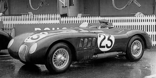
Somewhere on the trip home I conceived the Idea of recreating one of the original LeMans cars from 1951. I knew all three of these cars had been disassembled at the factory and I also knew that they had been a bit simpler than the later issue. They should, therefore, be easier to put together from available bits and pieces and their 1951 configuration would keep them from looking like just another replica.
I started to compare period photographs and illustrations with documentation of the later production cars. The later (1953) factory cars were left out of this comparison as they again were markedly different.
Certain basic facts showed up right from the start and constituted a level of general knowledge about these cars (XKC 001, 002 & 003 ). Current pictures clearly show the letterbox vents on the sides of the bonnet, the tapered louvers at the top and the bright trim rings around the headlamps. In the rear the position of the rear marker lamps was different and it was widely known that the frame was black and had drilled braces where the production cars had solid channels for the lower diagonal braces. Occasionally you would read about the 1 ¾ " carbs being fitted or the swaged firewall being unique to these cars. No doubt about it, they were different. But just how different? Was it possible through contemporary sources to determine the full extent of the individuality of these three cars.
I was off.
This study you are reading is in no way a completed work but has progressed far enough to demonstrate both its soundness and its historical significance.
I perused all the contemporary pictures I could lay my hands on and compared them with those of the later cars. I poured over text references and recorded any cite which was cross referenced by another source or where it lead to photographic verification. In the process I have amassed I excess of fifty images of the '51 cars alone.
What I have included here are a limited number of reproduced pictures plus footnotes which offer the substantiation of all the differences that have so far revealed themselves.
There appear to have been some internal differences even among the three cars. By way of example 001 appears to have been fitted with a vent on the oil filler, similar to some of the later cars, which is absent on the other two cars. (002 & 003)
The cars also underwent some degree of pre-debut evolution. The most well documented of these is the relocation of the bonnet straps from the sides to the top. It is my deduction, which is documented in the coachwork section, that the near side door was eliminated as an operating entity well before the cars headed off for Le Mans. The racing screen mountings and cowling and the rear-view mirror set-up also changed although the "original" set-up was probably for testing and there was more than likely no intention of competing the cars that way.
It needs to be remembered that from the psychological reconstruction standpoint these cars were put together in an extreme hurry ( "about seven months" according to Bill Haynes. (N-78)) and therefore each one probably differed in some detail from the others. ( Not that this was an unusual practice even on the assembly line.) These cars also probably borrowed heavily from the parts bin unless it was felt important to the goal to have bespoke parts provided by various suppliers such as Willmot-Breeden, Lucas, or Blumells.
There is a tendency, from our perspective, to think of these cars as part of a continuum and while that was indeed the intention, for some half year they soldiered on very much as one-off "specials" with all that that implies.
Further underlining the special nature of these three cars is that they were probably built at the Foleshill plant just prior to the relocation of production to the then new facility at Browns Lane.
One of the greatest mysteries of this whole undertaking is the lack of commotion it has engendered. In a climate where more and more subtle variations seem to be of greater and greater interest the dissemination of this treatise seems to have generated little or no response whatsoever.
The documented and illustrated outline for this article was shipped off to scions such as Sir Sterling Moss, Philip Porter, Terry Larson, as well as Julia Simpson and Ann Harris of JDHT.
I received a nice letter back from Sir Sterling avowing that he couldn't remember any details about the car, annoying or otherwise. Which from his point of view as a driver is perfectly logical particularly since the cars seem to have few if any memorable (read annoying) characteristics.
From the late and much missed Karen Miller I received the most amusing response saying that since I didn't own the car she was unable by company policy to provide me with any information. She referred me to Julia Simpson.
From the rest nary a word.
 THE ENGINE
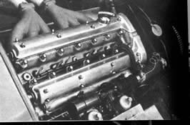
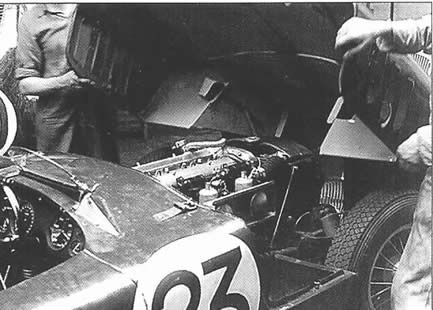
Beginning our analysis with the engine we notice that it has both the early studless cam covers (C-133) and the early Mills cylinder head with the Siamesed plug wells ( part# C2242, see D-20). This cylinder head cast by the William Mills Co. Was most often fitted to the XK120 whereas the cylinder head with the separate plug wells was cast by the West Yorkshire Foundry and was seen most often on the MKVII. A stock high tension wire loom (D-20) carries the spark from one of two coils mounted closely together above the 1 3/4" carburettors (C-132) on stock coil mounts. This use of the stock fibreboard loom was a bit of a surprise to me since I would have thought there would have been closer attention paid to the possibility of crossfire within the loom. Obviously this was thought of later since by the time we get to the 53 cars the wires are well separated. One wonders what the experiential background that lead to this arrangement was. The dual coil configuration carried over to the ill fated 1952 configuration (001, 002 & 011 see C-171 (looking at the head this is probably of 011)) but it is interesting to note the coils were now spaced farther apart which probably meant different brackets. I'm assuming the motivation for the extra separation was that if and when a changeover was necessary the working tolerances using the stock mounts was nothing if not close. The block was presumably right out of stores, painted black except for the core plugs and oil gallery plugs which remained unpainted. This latter fact would indicate that even if the casting came out of inventory a good deal of care was exercised in its assembly. I have a theory that the production road car chassis were "blown over" with gloss black paint subsequent to major assembly and that this is what covered over a lot of the subpart individuality. ( Oxide bolt heads, manufacturers colour coding marks, etc.) And has subsequently lead to a lot of chromatic confusion. There was obviously no impetus to do this on the Le Mans cars so all of the bits seem to appear in their parts bin finishes.
The engine mounts were of the "later" style mounted to bosses on each side of the block. The presence of these mounts would indicate the use of the C4820 block which went into production in January of 1951. From November of '51 the block was modified to accept the installation of the Bray block heater. I am assuming that this was the unit fitted to the "production" C-Types but not to the cars in question.
I suffered a momentary flight of fancy during which I thought that there was a possibility that the pan used on the first cars consisted of a 3 ½ Litre pan ( P-27) turned end on and mounted via an intermediate aluminium spacer. In spite of this aberrant line of thought the aluminium pan actually used seems to bear a close resemblance to the one employed later on, (C-133) there does not appear to be, however, any evidence of a by-pass hose to the area where the hammerhead section of the subpan should be. The specific configuration of this sub pan may have been carried over to the later cars or maybe not. I don't have a clear picture of this area.
I have a mysteries list and the pan configuration is on it. (Are you listening JDHT?)
A number of years ago I was striving to replicate the observation platform awning mechanism for the conversion of a Pennsylvania Railroad passenger car that I own. I came up with at least three possible solutions for the way the awning was attached and retracted. None of them resembled the simple yet elegant method I ultimately discovered they used. The great lesson here is that making inferences about the unknown is truly risky business and that your time is better spent doing good solid research than doing the most creative of speculation. What ever it looked like this alteration to the pan was what resulted in the modification to the oil pickup that failed in two out of the three cars. (F-10 para. 8) There has always been the assumption, at least on my behalf , that this failure was somehow related to a production condition. This was in fact all new work, as the use of copper piping in that area would suggest, and it goes a ways in making that close call in 1951 more understandable. I've always quietly wished the cars had come in 1,2 & 3 if only to satisfy my sense of poetry.
The inlet manifold appears to be stock with all the heater openings and the aforementioned otter unit location blocked off and safety wired.
The exhaust manifolds on the other hand were bespoke units which eliminated the sharp bend coming out of the head and appeared on these first cars in raw cast iron as opposed to some of the later production cars which seem to have been porcelainized (M-93).
The oil filter looks to be the standard Tecalemet short canister unit first introduced on the MKVII with the throttle return spring tab under the upper right hand mounting bolt in a typically agricultural fashion. I've never understood the 120's solution of hooking the return spring over the starter brush cover clamp bolt. It works but somehow I can't help feeling the solution should have been a bit more elegant.
Most of the plumbing and wiring hold downs fitted to the engine appear to be out of the parts bin as we might well expect.
The carbs were 1 ¾ stock units with RG or RC needles I'm certain they must have had different internals in the form of jets, springs etc. but have been unable to find out what those specifications were. They appear to have retained the thermo starting unit on the rear carb ( and since the otter switch location is blanked off and safety wired it seems logical to assume that this was operated by a switch from the cockpit (C-132). Its interesting to note that the factory didn't seem to trust the otter switch any more than we do now.
The waterpump appears to have been standard issue with all the heater connections blanked off with threaded plugs as opposed to untapped as on the later cars. The pulley appears to have been that fitted with the cast aluminium fan and, being of a larger diameter than the later pulleys would have had the effect of reducing the pump speed at high RPM's. The belt was the same cross section as the production issue although of a presumably greater length to accommodate the larger pump and dynamo drive pulleys. This wide belt was carried through onto the 52 versions but seems to have died out along with the change from grease fittings to sealed pump bearings.
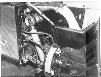
The most noticeable difference, in the cooling department, between the first Le Mans cars and those that followed was the presence of the old, time honoured, crank hole through the radiator. This most likely means that another engine difference is the presence of the eared damper mounting bolt on the end of the crankshaft. I hope this was for ease in tuning or setting the timing and not really in the contemplation that someone might try to crank start the engine. It's not sure how the centre mounted foglamp would have interfaced with any cranking effort but it's something to think about.
It's difficult to discern much about the bell housing but we do know that these cars had the standard fitment clutch with the exception of the elimination of the springs ( of "solid centre" fame) in the drive disc assembly which had caused so much grief for Ian Appleyard in previous outings with the 120. Presumably a then current production flat bottom bell housing was used.
A good number of details, while different from the road cars of the day, became standard for the competition cars that followed and often then as special equipment and sometimes standard equipment for the street cars. This was certainly true of such items as the flywheel and clutch assembly and therefore they have not been treated here as a "difference" although they were in fact so at the time the cars were put together. I'm actually amazed that some of these upgrades took as long as they did to reach the street. To Jaguars credit the improved brakes were introduced the most rapidly (in April of 1952) but the rest of the upgrades took some time to filter into the system, being available on the special equipment models first and later adopted, for the most part, to the production cars.
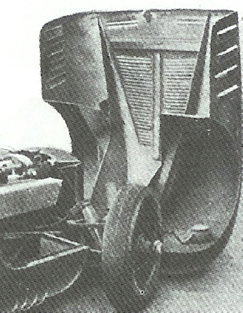
The gearbox appears to be a long tail case unit resembling a HS or JS unit most commonly appearing on the MKVII saloons. Presumably this was fitted with close ratio gears and in most respects resembled later fitment. The cover is unique to the C-Type and sports one of the features unique to the first three cars. During initial testing the conventional breather appears to have sprayed oil around the cockpit and over Peter Walker in particular. The resulting solution was the adaptation of the so called "pig's tail" vent in which a curlicue of copper pipe rises vertically if less than majestically from the gearbox cover. This ingenious and effective spiral vent is a testament to the fact that there wasn't much time on this project for fancy or elaborately engineered problem solving. ( E-1 )
PROPELLER SHAFT
Presumably the prop shaft was identical to later issue and if not I'm not sure that it matters very much anyway. This aspect of the three cars may well fall in the same category as a piece of toy train equipment I've been searching for for years. There is a Gondola made by the Lionel company which was equipped with wheels which have the same swirl pattern found, in this country, on the prototype. One of the price guides explains the remarkably low price of this hard to find variation saying "A rare variation, but nobody seems to care."
The rear axle is another of those items that differed from then current practice but not much from the later cars nor, ultimately, from later 120 production specification. This new use of the Salisbury axle was probably driven by the adaptation of the centre lock wire wheels which would have been an awkward and complex fit up to the then current ENV unit.
The location of the axle by triangular torque reaction arm differed from the later production cars but not from the early series C-Types. The reaction arm continued on after the first three cars until it began to show its weakness on rougher surfaced tracks and in road racing and was subsequently replaced. In a lot of cases the later control arms and panhard rod have been retrofitted to earlier production cars.
The steering as with all the C-Types was by rack and pinion. There was nothing particularly new about this type of steering . It shows up on mid nineteenth century steam tractors and was the system used on the Benz motor wagon. This was a first for the folks at Jaguar however, since they had, up to this date, used the newer (1930's) recirculating ball system.
Based on subsequent development I am assuming that the unit used closely resembled that employed on the production cars and the Alford & Alder unit ultimately specified on the XK140.
Whether the front suspension forgings were different from the production MKVII and XK120 units has yet to be determined. I've read commentary stating that the C-Type a-arms were wider based than the stock 120 or MKVII but I've assembled a wider base unit by mixing parts from the MKVII and 120. Whether this was true on the first three cars is a matter for some debate. My personal opinion is that since the cars went together so rapidly and seemed to demonstrate only the most moderate handling abnormalities in tests. The original road testing took place late enough in the day to have made major suspension redesign unlikely. Visual comparisons seem to indicate that at least the same upper wishbone parts were used on the early and late cars. (B-44 & 45) Until some kind soul provides me with shop drawings showing altered units on the first cars the jury shall remain out.
As far as I have been able to tell the rear suspension resembled that of the subsequent cars with the partial exception of the previously noted torque reaction arm.
BRAKES
This was the first appearance of the Lockheed self adjusting front brakes. While this again was a departure from the then current 120 street cars it became the norm for the subsequent C-Types and ultimately was adopted for all the drum brake cars.
Having dealt with the manifolds in the engine discussion all that remains is the mufflers and plumbing itself. All appears to be as with the later cars with the exception that the flex section in the exhaust system itself appears to have been located immediately ahead of the muffler assembly as opposed to just past the manifolds on the later cars. On 001 and 003 it also seems that the pipes were wrapped with asbestos shielding, a process which was omitted on 002 and the production cars.
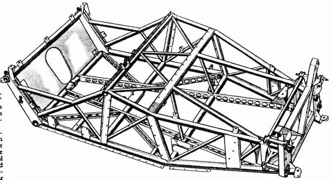
As you might by now have come to expect the frames of the first three cars were markedly different from the assemblies that were to follow. Some of the differences such as the black colour and the diagonal race lightened braces are relatively well know but there were a goodly number of other differences which are relatively easy to document and doubtless a vast number of additional small variations that would show up if one were allowed the now impossible luxury of a close inspection. There is also the distinct possibility that there was some evolutionary development within the frames. The cars seem to have been built serially rather than simultaneously with, appropriately enough, 001 being the first to be ready. I would certainly expect that there was some form of learning curve as these cars went together and what more logical place for this to have manifested itself than in the frame.
Original 1951 frames seem to have been put together from 16 ga steel rather than the 18 ga of the later cars. (H-118) Whether the frame was brazed or welded seems to be a matter of some discussion. (A-22 par. 1 vs. A-22 par. 2&3) There are references to both being used. Its even possible that 001 was brazed for ease of fussing around and 002 and 003 were welded. Photographic evidence seems to support the welding theory there being ample evidence of Jaguars somewhat less than beautiful welds.
The physical differences range from the obvious to the speculative and some alter the very perception of the way the cars were constructed.
The rear shock mounting and petrol tank forward attachment were different
The shock mount seems to be by separate welded on tabs and the fuel tank mounts project up above the frame. (A-24).
The body shell was mounted to a a series of linear flanges fastened flat to the tube frame and drilled with a series of mounting holes rather than to a series of discrete pickup points (Again A-24). This is similar to the flange attached to the cowl area on the later frames but with a more liberal use of mounting bolts holes. The bottom rails fore and aft of the scuttle, the dash cross member and the dash side support struts all seem to have had these flanges.
The often cited perforated diagonal braces seem in reality to have supported some form of floor at least forward of the seats. This explains why the full extent of these diagonal braces doesn't show forward of the seats in pictures.
There seems to have been provision for a standard fitment 120 jack (B-52)
The forward edge of the body tub immediately aft of the front wheels was supported by a wide vertical flange in place of the two triangular gussets on the later cars.
The road wheels seem to be of the same alloy rimed configuration as the later or production cars and since the thrust of this study is the documentation of the differences and not so much the similarities between the cars they will not dealt with in any detail here.
I have treated this as a separate category due to the large number of differences in this area alone.
It is the louver arrangement which is probably the most recognisable characteristic of the early cars so I shall start with these.
The so called letterbox louvers on the sides of the bonnet assembly appear to have an interesting evolution of there own. In the very early pictures (J-86, of 001 these vents appear quite clearly to head inward into the interior of the car. It also appears that it was in this configuration that the bonnet latches were located. In the later pictures when the direction of the vents has been reversed it is readily observable that their was a "bite" taken out of the second louver to accommodate the release handle in its vertical position. From the look of the "crispness at the base of these later louvers it would seem that they were individually formed and fastened onto the holes where the old inward facing louvers had been. As to what the reason for this early modification was I can only speculate. Two theories come to mind. It is possible that it was discovered that the early design which had the semblance of sleekness and in some minor way cut down on the frontal area did not scavenge as well as the outward facing item. It also may be that the inward facing louvers behaved like the fipple of a wind instrument turning the C-type into some sort of bizarre and annoying musical instrument. The car was tested out with the inward facing louvers as can be seen in the photograph of an early track test with the car (Presumably 001) wearing a factory plate 164 WI (O-92). Interestingly enough, at this stage the row of louvers in the lower panel seem to have not yet made their appearance. It is additionally intriguing to note that one of Malcolm Sayer's wood models for the car shows the tapered top bonnet louvers of the original cars but has the finer louvers of the later cars indicated on the side panels. ( C-129)
Another, and in some respects more major difference has to do with the very structure of the bonnet itself. A careful look at the now famous picture of the Hotel de Pais garage (B-16&17) shows car No23 (001, produced first) with a complete tubular structure forming the bonnet frame! (S-25, above right, shows another view of this tube frame.) The picture in the Autocar of July 13th of 1951 (F-6 above left) shows car 20 (the winner) with a more developed assembly with the internal mud guards and what appears to be tube reinforcement around the rear edge and bottom.
At the rear edge of the later bonnets there was a flange or top hat stiffener that was contoured to the shape of the top edge of the scuttle assembly it mates up to. On the first cars this reinforcement appears to be welded tubing which extends forward under the louvers where the later units have a wired edge.
Another interesting glimpse is to be had in the Autocar picture (above) in that it shows what appear to be the headlamp buckets modified at the last minute to accommodate the upgraded Marchal headlamps.
The tapered louvers on at least the first car appear to have been applied separately (D-20) and this was likely true of all three.
The most often talked about difference in the '51 body assembly is the apparent presence of a second or passenger side (left in this case) door. The word apparent is used advisedly inasmuch as all evidence points to this door being vestigial right from the early stages. The examination of contemporary pictures seems to indicate nothing more than a shell on the left hand side with none of the interior structure and nothing more than a vertical rib for stiffness. (E-6&7)(Q-95). Even at the body in white stage of 001 while it still had it's inward facing bonnet vents there are no sign of any hinges on the mechanics side. (R-16).
While indirectly on the subject of door hinges it's interesting to note that the door hinges on the drivers side do, themselves, differ from later production. While the early cars had hinges with relatively long equal leaves front and rear (C-139) the later units have a distinctly shorter leaf on the forward side. I have asked around as to what various people thought might be the original application for these hinges but have yet to find a source. I'm sure they were whatever Willmot Breeden could find out back that filled the bill. Presumably whatever spares bin these first hinges were pulled out of had a limited number in it.
The four smaller lower scuttle vents seem to have made their appearance somewhere around the time that the direction of the bonnet "letterboxes" was changed. This might have been the result of some real or anticipated overheating but I find no documentation that mentions overheating problems. and the presence of the spotlight in front of the radiator would seem to counter indicate it. (Altho the '52 cars had the same spotlight mounting initially and we all know about them!) One picture of 001 with the bonnet raised shows the later vent arrangement and a blanking plate across the top section of the radiator. I suppose that the cooling configuration could have changed when the inner mudguards were added and all the cars were modified to fit the new conditions which may have rendered 001 overcooled!
I see no particular sign of the body shape evolving as it went into production but it would not surprise me. Jaguar has a time honoured tradition of "tinkering" (witness the changes between the alloy and steel 120's.) For them to have taken a nip here and a tuck there as the car geared up for manufacture would almost seem a forgone conclusion. We know there were changes in the rear to accommodate the altered light layout but I am also intrigued with the apparent difference in contour between the previously noted picture from the Lister-Jaguar book (R-16) and later pictures altho this could be the camera angle or have some other similar illusionary basis.
The floorboards appear to have been mounted on top of the drilled floor members hiding the wiring and some of the controls between the belly pan and floor. (F-9)(E-1)(B-43) ("Below the metal floor is a thin space just sufficient for control rods and pipes,..." F-9 ) Particularly note the flange at the base of the transmission tunnel sitting on to p of the frame members in B-43. The tunnel itself had square corners where it screws to the bell housing cover as opposed to the rounded corners later on.
The presence of the swaged section at the top of the firewall is more commonly remarked on but 001 and possibly 002 seem to have had the intersections of the reinforcing tubes welded those on the later cars having a gap between the ends of the diagonals and the verticals. (C-133)
Another detail worth noting in the pictures mentioned above was the complete absence of any carpets or padding. This extended to the apparent lack of a gearshift and brake lever boots. I guess they figured that with no other weather protection what was a bit more water from a different direction. Also whereas the later cars have light colour sheet metal where it shows in the cockpit it would seem that the LeMans cars were all over sprayed black inside.
There are a number of first hand references to the seats being "covered in cloth" (F-9) There is also a picture of Peter Whitehead sitting in XKC 039 on cloth seats in the Nov./Dec. Jaguar Quarterly of 1991 (Page 77).
The bonnet latch pin at the very top of the firewall is merely a projecting pin on the first cars and has a sheet metal bracket on the later cars.
Again there are a number of variations which, empirically, would lead to the conclusion that the wiring harness itself was different. It is to Jaguars credit that an actual harness seems to have been assembled. It would have been very easy given the timetable for the wiring to have ended up as a bundled collection of individually run wires but a fair amount of care seems to have been taken to keep things neat. Most of the wire seems to have been gathered together with the vinyl sheathing which became prevalent on the later cars such as the MK2. It is a fairly safe assumption that the standard Lucas / Jaguar colour coding was employed.
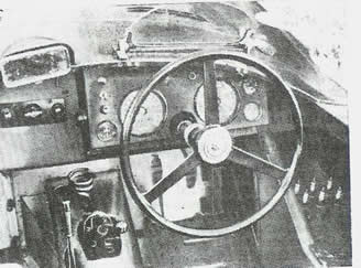
A. LIGHT SWITCH ( PANEL)
B. RUNNING LIGHT SWITCH
C. LIGHT SWITCH (FOG LAMP)
D. HORN BUTTON
E. THERMO CARB SWITCH ( F-9)
F. IGN. KEY
G. STARTER BUTTON
H. AMPMETER
I. SPEEDO
J. IGN. WARNING LIGHT
K. HIGH BEAM WARNING LIGHT
L. TACH
M. DUAL GAUGE
N. FUEL GAUGE
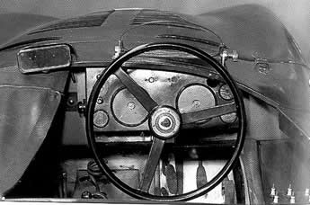 There are at least two electrical mysteries which have cropped up. The location of the dimmer switch and the front parking lamp arrangement. Presumably the cars were fitted with both. In order to be road legal and comply with the FIA regulations there must have been some provision for both. There is some marginal evidence that the dimmer switch was located off the instrument panel to the right but this has certainly not been confirmed.
The later arrangement of a marker lamp lens and frame mounted at the base of the headlamp assembly and under the outer lens does not seem to have been employed. The headlamps themselves would have been the approved Marchal units which proved to be limited in there ability and were replaced at Lofty England's insistence with more powerful units just before the race. These replacement lamps apparently necessitated a bit of "field engineering" to make them fit (see bonnet section ). The marchal lamps that say Le Mans on the lens are contemporaneous to all of this but it is most likely they represent the replacement units and not the outmoded ones specified at first. The headlamp frames themselves which were also unique to these cars are recorded by one source to have been aluminium which on the whole makes some sense. (H-126)
The single low mounted tail lamp on either side is a well known characteristic and the Lucas #488 lamp units seem to be right out of the 120/MKVII spares bin.
As I pointed out at the onset this analysis is based on published information. Hopefully given better access to archival material I will be able to expand the scope and detail of this "dig", address some of the identified mysteries and almost surely discover a few more.
Once I have a better picture of what these singular cars looked like maybe I can get back to where this all started and put one of these cars together. You see I've been collecting all these parts and.....
A- PORTER: JAGUAR SPORTS RACING CARS
B- JAGUAR QUARTERLY: C-TYPE ISSUE DEC. 1991
C- WHYTE: JAGUAR SPORTS RACING & WORKS COMP. CARS
D- ROAD & TRACK SEPTEMBER 1951 (PAGE 20)
E- AUTOCAR: JUNE 13, 1951 REPRINT PAGES 1-4 (SEE BACK OF A )
F- BROOKLANDS "ROADTEST" JAGUAR C-TYPE & D-TYPE
G- LE MANS "THE JAGUAR YEARS" 1949-1957 BROOKLANDS BOOKS
H- JAGUAR SPORTS CARS; PAUL SKILLITER
I- http://www.as.net/~rdfrantz/SportsCars/Gallery/
JAGCTYPE_LEMANS.JPG
J- VIART & COGNET: JAGUAR A TRADITION OF SPORTSCARS
K- PROFILE PUBLICATIONS #36: THE JAGUAR C-TYPE
L- JAGUAR WORLD Vol.13 # 8 Sept, 2001 pgs 24-27
M- CLASSIC JAGUAR WORLD Vol.13 # 11 Dec., 2001 pgs 76-95
N- JAGUAR SERVICE MANUAL for ALL MODELS 1946-1948
O- THE JAGUAR TRADITION, MICHAEL FOSTRICK
P- THE DUNDROD TT RACES 1950-1955, JOHN S. MOORE, DREOILIN
Q- CLASSIC JAGUAR WORLD Vol.11 # 11 Dec., 1999 pgs 95-96
R- LISTER - JAGUAR C-TYPE AND D-TYPE, UNIQUE MOTOR BOOKS
S- CLASSIC JAGUAR WORLD Vol.13 # 8 Sept., 2001 pgs 24-27
T- THE RISE OF JAGUAR, BARRIE PRICE